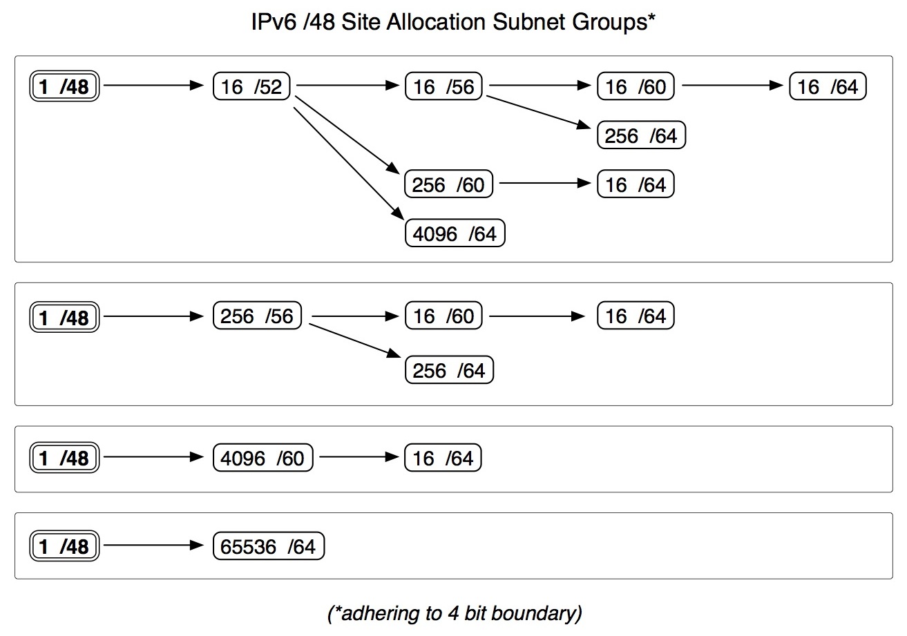
Following up on my last post, the vast size of a single site /48 allocation often creates anxiety for network architects creating an IPv6 addressing plan. This anxiety arises from two conflicting goals in address planning: address conservation and address plan consistency (leading to operational efficiency). It is difficult to achieve the latter when the former is the primary criterion.
But years of planning network addressing in IPv4 have made it difficult for network architects to accept the apparent windfall of abundant addressing allowing for address plan consistency and efficiency in IPv6. Thus, the inclination to partition a /48 to address many sites is a persistent one. Finally accepting that it’s not necessary to share a /48 among sites still leaves the challenge of what to do with all those subnets.
Fortunately, the current best practice of adhering to the nibble (4 bit) boundary in grouping IPv6 subnets constrains the number of possibilities available in carving up a per-site /48. Figure 1 shows an illustration of the combinations possible.

Figure 1
Remarkably, when adhering to the nibble boundary, there are only eight possible consistently hierarchical subnet groupings. As discussed in my recent posts, the goal of address plan consistency leading to operational efficiency is greatly facilitated by geographical and/or functional groupings. Thus, the task of choosing among the eight possible groupings should be made easier by matching the site topology with the most appropriate subnet grouping (it may be helpful to begin thinking about grouping topology elements in 4 bit multiples; e.g., 16, 256, 4096, and 65536).
As an example, imagine a campus LAN with 5 buildings. Each building has a similar VLAN topology with wired, wireless, guest, VoIP, and at least one VLAN with unique function. If there is only one level of VLAN or L3 aggregation for the campus one option would be to simply pick the first grouping of subnets sufficiently numerous for the total number of VLANs — in this case, 16 (or a /52 per VLAN). The first /64 for each of these /52s could be set assigned to the L3 interface on the aggregation router or switch.
But it might facilitate operations and troubleshooting to be able to immediately identify the location of an address (as well as the function of the VLAN) by looking at the prefix. We could thus assign a /52 to each building (also setting aside a /52 for infrastructure and leaving 10 /52s for future use). That would leave 16 /56s per building for VLAN assignment. Our example has 5 VLANs deployed in its topology, leaving 11 /56s for future use. Each VLAN /56 would have 256 /64s for interface assignments.
Thus, if our site allocation was 2001:db8:aabb::/48, we could make the following assignments:
Site infrastructure: 2001:db8:aabb::/52
Building 1: 2001:db8:aabb:1000::/52
Building 2: 2001:db8:aabb:2000::/52
etc.
Wired data VLAN, building 1: 2001:db8:aabb:1000::/56
Wireless data VLAN, building 1: 2001:db8:aabb:1100::/56
Wireless data VLAN, building 2: 2001:db8:aabb:2100::/56
etc.
Inherent in this approach is a critical aspect of IPv6 address planning that takes advantage of the hierarchical consistency that is unique to IPv6 given it’s large address space. Namely, that subnet prefixes be the same size at each level of the hierarchy. For instance, in our example, a /52 is always a building, and a /56 is always a VLAN. (Note that this concept is already applied generally in IPv6 given that a /48 is always a site and a /64 is always an interface assignment).
As always, please feel free to share your own IPv6 address planning efforts in the comments.


