Introduction
In part one, we started our discussion of IPv6 prefix allocation methods with the simple reason of why you need them in the first place: a properly sized IPv6 allocation provides a vast amount of IPv6 space and you need to have one or more methods for logically and sensibly dividing and assigning that space based on the types of networks you are addressing. I also listed the four most common methods of IPv6 prefix allocation: next available, sparse, best fit, and random. Part one concluded with a detailed look at the next available allocation technique. If you haven’t read part one and are unfamiliar with IPv6 address planning, I encourage you to read it before reading this post.
In part two, we’ll discuss the remaining IPv6 prefix allocation methods along with how and when to use them. As with our example in part one, the idea is that you’ve been allocated a sufficiently large block of IPv6 addresses to meet your IPv6 addressing needs for decades.
Since we covered the next available prefix allocation method of assigning prefixes (i.e., subnets) of IPv6 address space in detail last time, this time we’ll focus on the three allocation methods that remain. They are:
- Sparse
- Best fit
- Random
Sparse Allocation
The simplest description for sparse allocation of IPv6 is the assignment of prefixes with lots of additional unused prefixes (and thus address space) in between them. The basic benefit of this method is not simply leaving space in reserve—after all, it likely wouldn’t be that hard to find available extra IPv6 address space from within the overall IPv6 allocation. What sparse allocation provides is address space in reserve that is more likely to be contiguous.
Fellow routing nerds may recognize immediately that such contiguous space adjacent to the original allocation and reserved for the original allocation’s recipient, is better for enabling route summarization and reducing the size of routing tables (i.e., preventing large prefix disaggregation). That is precisely why sparse allocation is preferred for service providers that need to allocate large blocks of address space to their customers. And of course, organizations such as the Regional Internet Registries and IANA which are tasked with allocating all IPv6 (and IPv4) addressing to those service providers (and more frequently than before, directly to enterprises) benefit from using sparse allocation mode to guarantee contiguous space held in reserve for any and all allocations.
For example, if an enterprise is allocated a /32 of address space from ARIN (the RIR for North America), it is very likely that such a /32 was allocated from a larger allocation held in reserve for that enterprise. Keep in mind that the enterprise developed enough of an address plan to recognize that they needed a /32 of IPv6 address space. They requested a /32 from ARIN and provided the necessary justification. ARIN approved the request and assigned them a /32. However, perhaps unbeknownst to the enterprise, ARIN reserved, say, a /29 containing 8 /32s, one of which was publicly assigned to the enterprise. If that enterprise needed more IPv6 address space at some point in the future—and as long as that need didn’t exceed the remaining 7 /32s—additional contiguous /32s up to the entire /29 could then be assigned to the enterprise.
Otherwise, the enterprise could certainly be assigned additional IPv6 space from another part of the RIR’s overall IPv6 allocation, but it would not be contiguous. It’s also possible that without contiguous space held in reserve for the enterprise, the RIR could require the return of the original allocation for the new larger one (hello, painful and costly renumbering of the entire network!). Most organizations are used to dealing with disaggregated and non-contiguous IPv4 prefixes, but it creates complexity in managing the address plan. Such complexity typically results in operational errors and more difficult fault isolation.
The above example applies equally well to service providers and their customers. Sparse allocation provides similar benefits. Keep in mind that service provider allocations are almost always Provider Assigned (PA), meaning that the allocation or any part of it is only permitted to be routed through that service provider’s network. (Compare this with the Provider Independent (PI) space RIRs assign, which are allowed to be routed through any provider.)
Here’s a visual example of sparse allocation to hopefully make the concept a bit clearer. Imagine that an organization starts with a /32 of IPv6 address space—in this example the reserved documentation prefix of 2001:db8::/32. The organization could be a Regional Internet Registry like ARIN (where the /32 would come from their much larger pool of a /12). Each entity being assigned prefixes from the /32 by ARIN would be some smaller organization requesting address space from ARIN.
Or the primary /32 allocation could belong to a service provider that has been allocated the /32 from an RIR. In that case, the entities receiving subsequent smaller assignments from the service provider would be their customers.
Another possibility is that the primary /32 allocation could belong to an enterprise. In that case, the entities might represent internal assignments to corporate network locations or regions.
In any of the above cases, the sparse allocation method would be to assign the first available /36 (e.g., 2001:db8::/36) to the entity while reserving some contiguous amount of address space. In our visual example, the equivalent of 3 additional /36s have been held in reserve for each of the first and second entities.
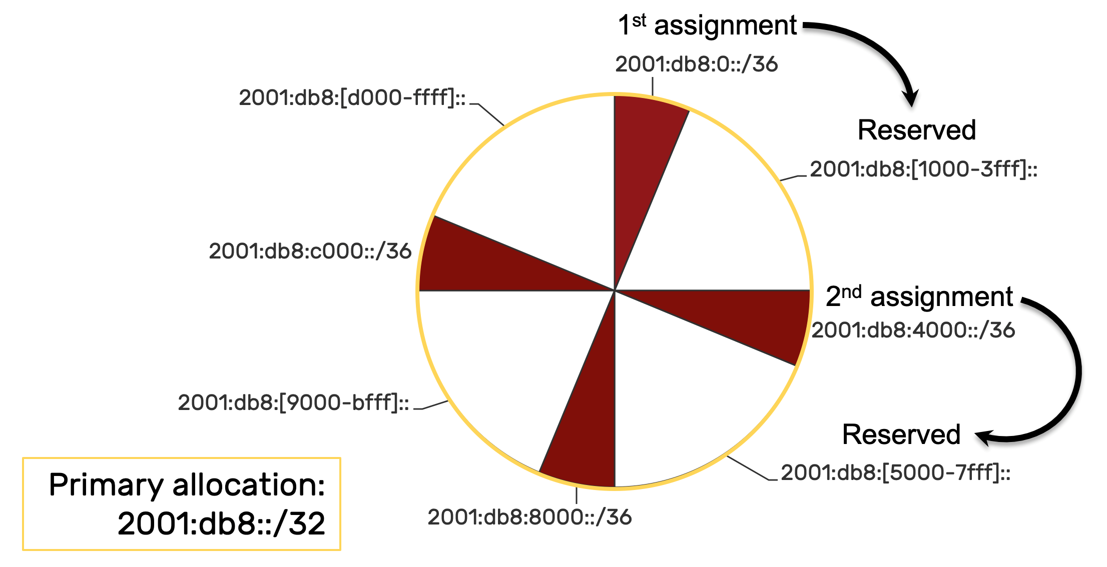
Let’s look at each step of the sparse allocation method in this example. The initial assignment to entity 1 is 2001:db8::/36. Keep in mind that because of zero compression rules for IPv6 addresses, the prefixes for the /32 and the /36 might end up looking exactly the same, but for the CIDR notation at the end of the prefix indicating the prefix length (e.g., 2001:db8::/32 and 2001:db8::/36).
You may notice that in the example graphics, I break this rule in a couple of ways. For instance, in the above graphic, to assist in highlighting the relevant nibble for the /36, I included one zero. In the graphics below, I included four zeroes in the first prefix example in the table column to help maintain a consistent prefix width for visual purposes. Technically, both these examples should be zero compressed to the minimum length (e.g., 2001:db8::/36).
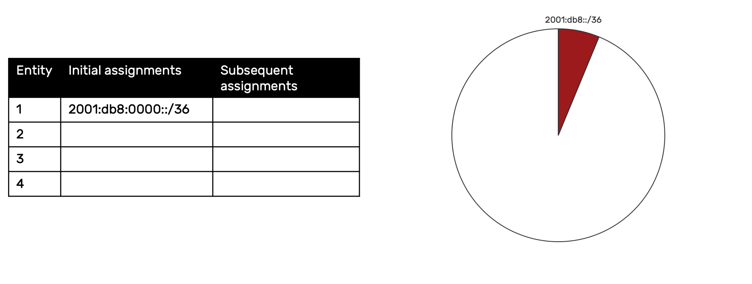
If you read part one of this blog, you may want to briefly recall how the next available allocation method works for comparison purposes. If we were using it, the next entity would get the next available /36, or 2001:db8:1000::/36.
As it happens, the underlying binary arithmetic and resulting bit manipulation for each method provides another perspective on how they compare. Since for either method we’re currently only looking at /36-sized prefixes assigned from a /32, we can restrict our bit manipulation to the most significant nibble in the 3rd hextet.
With the next available method of assignment, the next prefix would be defined by incrementing the least significant (rightmost) bits in that particular nibble. For example:
0 0 0 0 = 2001:db8::/36 (or with the relevant zero included 2001:db8:0::/36)
0 0 0 1 = 2001:db8:1000::/36
0 0 1 0 = 2001:db8:2000::/36
0 0 1 1 = 2001:db8:3000::/36
etc.
By comparison, sparse allocation increments the most significant (leftmost) bits in the nibble. Note that if this is done strictly, by incrementing one bit at a time, you’ll observe that it results in a sequence that skips the intervening prefixes in a way that isn’t necessarily intuitive. For example:
0 0 0 0 = 2001:db8::/36 (or with the relevant zero included 2001:db8:0::/36)
1 0 0 0 = 2001:db8:8000::/36
0 1 0 0 = 2001:db8:4000::/36
1 1 0 0 = 2001:db8:c000::/36
etc.
We can then reorder the assignments according to their natural decimal order to better align with our entity list order:
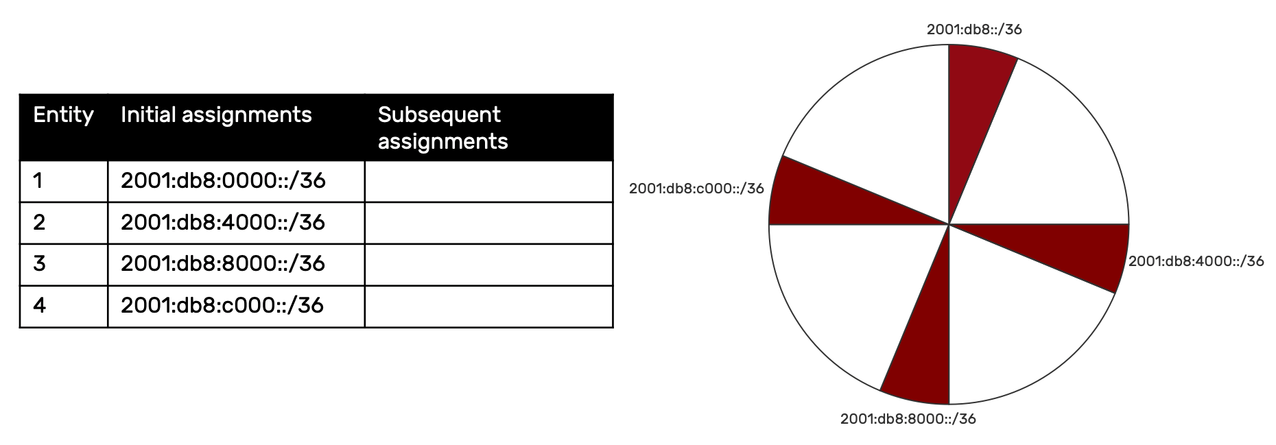
So how many entities can I assign /36s to? Well you may observe that once half (or eight) of the available /36s are consumed the sparse method is no longer possible for consistent assignment of remaining prefixes to the remaining entities. In this example, we’ll limit the number of entities to four, which results in each entity having 3 additional contiguous /36s in reserve.
Remember: the contiguous characteristic is definitional for sparse allocation! For example, by continuing to contiguously assign the remaining /36s to the respective entities, we get the following:
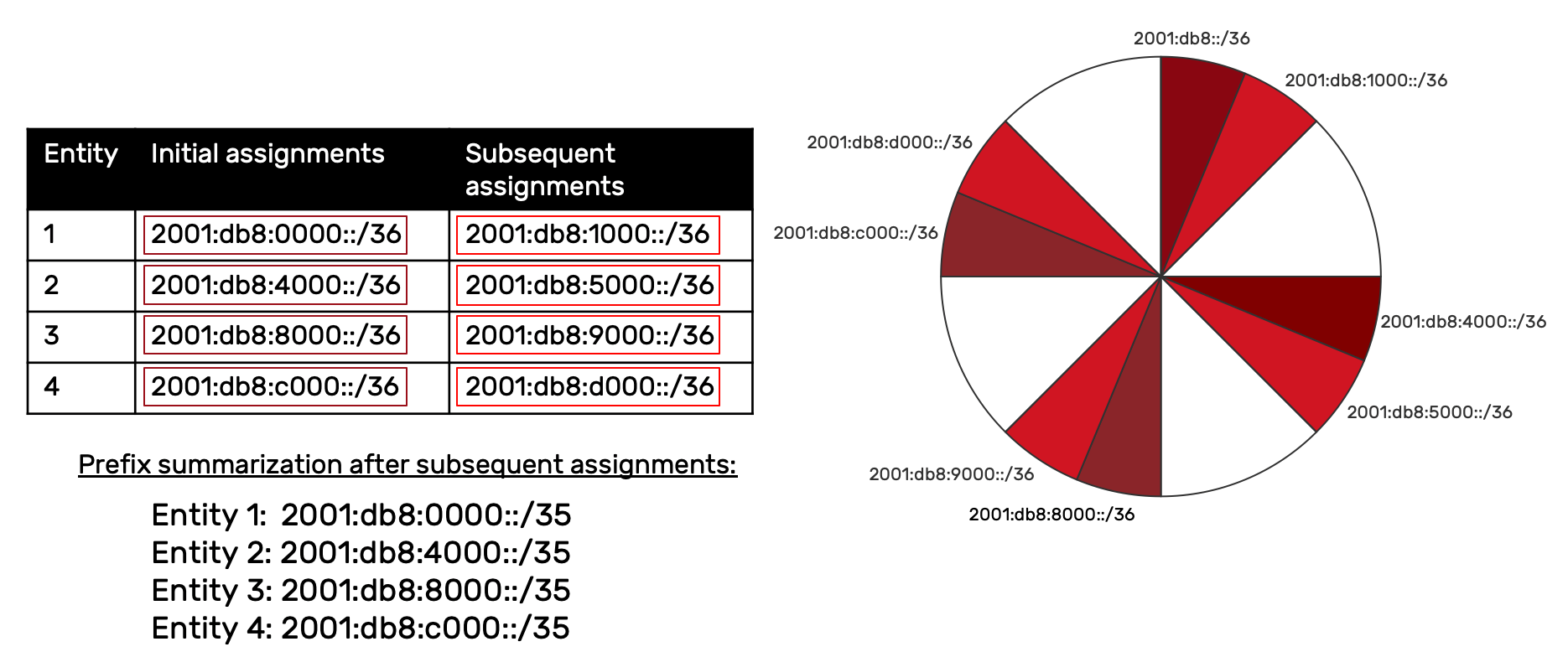
When all the IPv6 address space available in the primary allocation is assigned and the entire /32 consumed, each entity will have 4 contiguous /36s. As the above example suggests, these 4 /36s could each be summarized as a single /34. For example:
Entity 1 summary: 2001:db8:0000::/34
Entity 2 summary: 2001:db8:8000::/34
Entity 3 summary: 2001:db8:4000::/34
Entity 4 summary: 2001:db8:c000::/34
This summarization results in no more than 4 entries in the upstream router. By comparison, using any other method could result in as many as 16 routes. That should help demonstrate why sparse allocation is the method of choice for service providers and Regional Internet Registries (RIRs).
It may be obvious to you at this point that in our nibble-aligned example of a /32 divided into 16 /36s, any divisor that permits the assignment of an equal number of contiguous prefixes to each entity could be used.
2 entities = 8 /36s
4 entities = 4 /36s
8 entities = 2 /36s
Of course, we’re not limited to /32s and /36s. The sparse allocation method works just as well for other primary allocation sizes and could include groups of prefixes that don’t conform to nibble-aligned assignment as well.
Though sparse allocation is ideal for service providers, larger enterprises may find it useful as well. For example, an enterprise with locations in many regions supported by larger networks could benefit from using sparse assignments for each region. Future growth of those regions and networks could be accommodated with additional contiguous prefixes helping keep the routing table size to a minimum and simplifying configurations, operations, and troubleshooting.
The two remaining IPv6 allocation methods are best fit and random.
Best Fit
You’re likely intimately familiar with the best fit allocation method from IPv4, where it gets used frequently to conserve IP space—in particular, host addresses. In the best fit method, a prefix that provides the minimum number of smaller prefixes and/or host addresses (in the case of IPv4) is assigned from a larger primary allocation. In the process, as much as possible of the remaining primary allocation is preserved.
In this example, different entities are requesting the number of IPv6 address prefixes they have determined they need. To tailor the example to an enterprise, these entities could be functions or departments (e.g., data center, manufacturing, IT, etc.) responsible for their own networks and in need of address space.
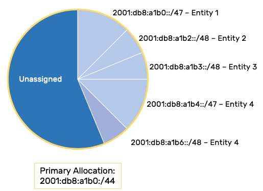
Entity one determines it needs more than one /48 but not more than two. The assignment that would “best fit” that request is a /47 (although it might be odd that a site may outgrow a single /48 and need two). Entity two needs not more than one /48 and receives a /48. Entity three also needs not more than one /48 and receives a /48.
Entity four determines it needs the equivalent of three /48s. Binary dictates that the prefix size has to be some integer power of two, so the assignment that would best fit entity three’s requirement would be one /47 and one /48.
All of this is perfectly reasonable in terms of meeting the basic requirement of a) having enough address space and b) assigning it according to current needs. But veteran network folk can spot the complications immediately.
For one thing our routing table will have the following entries:
2001:db8:a1b0::/47 – Entity 1
2001:db8:a1b2::/48 – Entity 2
2001:db8:a1b3::/48 – Entity 3
2001:db8:a1b4::/47 – Entity 4
2001:db8:a1b6::/48 – Entity 4
Of course these can always be summarized as the primary allocation prefix of 2001:db8:a1b0::/44 but within the immediate routing domain, we have to operationally deal with different prefix sizes, some entities having one prefix in the routing table with others having multiple entries.
By comparison, choosing the entity with the largest /48 requirement and assigning all the entities that size prefix allows us to meet the prefix/address space needs of each entity while reducing both the size and complexity of the routing table:
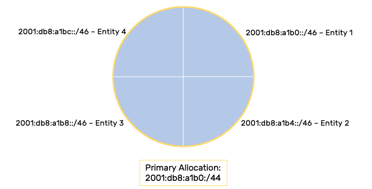
2001:db8:a1b0::/46 – Entity 1
2001:db8:a1b4::/46 – Entity 2
2001:db8:a1b8::/46 – Entity 3
2001:db8:a1bc::/46 – Entity 4
You’ll notice also that this allows us to use the next available allocation method.
This is typically the point where anxiety about “wasting” address space ramps up. “Entities 2 and 3 only need a /48! Why am I giving them 4 times that amount?!” The answer is that the practically inexhaustible supply of IPv6 results in the ability to make addressing and address plan choices that favor operational ease and efficiency over mere conservation for its own sake (a trade-off simply not available to us in IPv4 given its limited/exhausted supply): e.g., fewer routing table entries and greater ease of identification of network assignments—especially where allocations strictly conform to nibble boundaries (unlike our example immediately above).
Random
The final address allocation method we’ll discuss (if ever-so-briefly) is random. With random allocation, it’s typical to assign every entity the same size prefix but those prefix assignments are randomly selected. For example, a /48 provides 65,536 /64s. These /64 prefixes could be randomly generated and assigned:
2001:db8:a1b0:c290::/64 – Entity 1
2001:db8:a1b0:f0aa::/64 – Entity 2
2001:db8:a1b0:223b::/64 – Entity 3
2001:db8:a1b0:101e::/64 – Entity 4
etc.
This method would really only be useful or practical in a limited number of cases—specifically, where the allocation and provisioning process is highly automated and there is some additional benefit to random assignments (for reasons of security for instance, given an automated provisioning environment where the prefixes could be periodically reassigned with new random values). For example, a data center with different clusters that need unique IPv6 address space that will be routed to that cluster dynamically (e.g., Kubernetes).
If the last statement sounds (even vaguely) recognizable, it’s because a qualified example of this method is used all of the time—with “/128 prefixes”; i.e., individual IPv6 addresses! Privacy or temporary addresses are automatically provisioned via SLAAC and there is a presumed security benefit in preserving the anonymity of the IPv6 host (rather than having it be identifiable and traceable by the inclusion of its hardware address as part of the standard, non-random EUI-64 address assignment).
You’ve probably inferred at this point that when first designing (and with early iterations of) your IPv6 address plan, it’s unlikely that you’ll find much benefit to using either the best fit or random allocation methods. The best fit method is probably unavoidable at a much later date—hopefully much, much later—especially if you’ve designed your address plan based on a large enough initial allocation to provide abundant enough prefixes for consistent next available and sparse assignments.
Finally, it should also be pointed out that a good IPAM solution makes any of these IPv6 allocation methods easier to effectively manage. Fortunately, I can recommend a reputable DDI vendor that offers a high-performance solution in this area. 😉


